

Introduction

In civil engineering, surveying is the foundation of every construction project. Among the oldest yet most reliable techniques of surveying is the Compass Survey. Compass Survey uses a magnetic compass to measure the directions or bearings of survey lines on the ground. Because of its simple design, quick fieldwork, and low cost, compass surveying is still taught in colleges and remains useful in remote or rough terrains where advanced instruments are hard to carry.
For civil engineering students, learning a compass survey is essential to understand how to collect directional data for road layouts, canal alignment, forest mapping, and preliminary route planning.
In this article, you will learn about the Compass survey – its definition, working principle, types of compasses, required instruments, easy and step-by-step procedure, major benefits, and unavoidable limitations. So don’t forget to read the full article!
By the end of this article, you will have a strong understanding of not only how compass survey is performed in the field but also why it is still relevant as a basic surveying technique despite the rise of advanced tools such as the theodolite, total station, and GPS. Let’s get started:
What is Compass Survey?
Compass Survey is a traditional method of surveying in which the directions (bearings) of survey lines are measured using a magnetic compass. This technique helps in determining the relative positions of points on the ground by recording the horizontal angles between survey lines and the magnetic north.
Unlike modern instruments such as the theodolite or total station, the compass survey is simple, portable, and quick to use in the field.
It is particularly useful in areas where:
- The terrain is hilly, forested, or difficult to access,
- High accuracy is not critically required, and
- A low-cost and fast method is preferred for preliminary surveys.
In most civil engineering work, compass surveying is used for the following purposes:
- Preliminary route surveys for roads, canals, and pipelines,
- Boundary marking of plots or agricultural lands, and
- Mapping of forests, riversides, or remote regions where other instruments cannot be transported easily.
👉 In simple words, Compass Survey is all about finding the directions of lines and plotting them on a map using bearings measured with a magnetic compass.
Principle of Compass Survey
The principle of compass survey is based on the fact that a magnetic needle always aligns itself along the magnetic north–south direction.
When a surveyor sets up a compass on a point and sights another point through the compass, the horizontal angle or bearing of that survey line can be measured with respect to the magnetic north.
- The magnetic meridian is the reference direction.
- The bearing of a line is the angle between the line and the magnetic north.
- Bearings of all lines of a survey traverse are measured in the field.
- With these bearings and the measured lengths of the lines, the relative positions of points can be plotted on paper.
Types of Compasses Used in Surveying
In compass surveying, two main types of compasses are commonly used in the field.
Both are designed to measure the bearing of survey lines but differ in their construction, graduation system, and usage.
1. Prismatic Compass
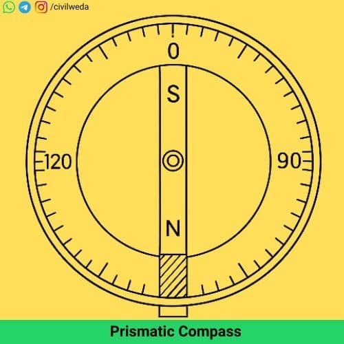
The Prismatic Compass is the most widely used in field surveying because it allows the surveyor to take readings and sight the object simultaneously. A Prismatic Compass is shown in the figure.
Features of Prismatic Compass
- Fitted with a graduated circular ring made of non-magnetic metal.
- The graduated circle is fixed to the magnetic needle and rotates with it.
- The graduations are marked in the Whole Circle Bearing (WCB) system, ranging from 0° to 360°, measured clockwise from the magnetic north.
- A prism is attached to the compass for magnifying the readings, hence the name Prismatic Compass.
- Light, portable, and easy to use in rough terrain.
Uses of the Prismatic Compass
- Suitable for quick surveys in large open areas.
- Commonly used for preliminary route surveys, topographic surveys, and reconnaissance work.
2. Surveyor’s Compass

The Surveyor’s Compass is an older type of compass and is now less commonly used than the prismatic compass. A Surveyor’s Compass is shown in the figure.
Features of Surveyor’s Compass
- The graduated circle is fixed to the box of the compass, not to the magnetic needle.
- The magnetic needle is free to move over the graduated circle.
- The graduations are marked in the Quadrantal Bearing (QB) system, where bearings are measured from either the north or the south towards the east or west (0° to 90° in each quadrant).
- It has sighting vanes instead of a prism for reading the bearings.
- Slightly larger and heavier compared to a prismatic compass.
Uses of Surveyor’s Compass
- Preferred for traditional land surveys and small-scale fieldwork.
- Still used in some educational institutions for training purposes.
| Feature | Prismatic Compass | Surveyor’s Compass |
|---|---|---|
| Reading System | Whole Circle Bearing (0°–360°) | Quadrantal Bearing (0°–90° each quadrant) |
| Graduated Circle | Fixed to the compass box | Through a prism (magnified) |
| Reading Style | By direct sighting through the vane | By direct sighting through vane |
| Accuracy | Higher | Moderate |
| Field Use | Preferred for modern fieldwork | Mostly for teaching/training |
Instruments used in Compass Survey
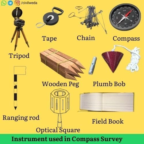
To carry out a compass survey, a few essential instruments, as shown in the figure, are used. Each of them plays an important role in making the survey work smoothly, accurately, and reliably. The instruments used are listed below:
Compass
The compass is the primary instrument used to measure the bearings or directions of survey lines. A prismatic compass is usually preferred in fieldwork because it is lightweight, portable, and allows the surveyor to sight the object and read the bearing at the same time. In traditional surveys or for training purposes, a surveyor’s compass may also be used, but it is slightly heavier and slower to operate.
Tripod Stand
The tripod stand supports the compass during the survey. It provides a steady and level platform for taking readings. Its three adjustable legs make it easy to set up on uneven ground, ensuring the compass remains stable. Without a proper tripod, accurate measurement of bearings becomes difficult.
Chain or Tape
The chain or tape is used to measure the horizontal distances of survey lines on the ground. Chains of 20 m or 30 m length are commonly used because they are durable and can withstand rough terrain. In open areas, a steel or fibreglass tape is often preferred because it is lighter and more flexible.
Ranging Rods
Ranging rods are 2 to 3 metre long poles, usually painted in alternating black-and-white or red-and-white bands for high visibility. They are placed at the survey stations or along the lines being measured so that the surveyor can sight them clearly through the compass. Ranging rods help maintain straight survey lines over long distances.
Pegs
Pegs are short wooden or metal stakes, generally 15–20 cm long, driven into the ground to mark the station points. These pegs help to identify the exact locations where the compass was set up or where a measurement started and ended. They are particularly useful when the survey continues for several days.
Arrows or Chain Pins
Arrows, also called chain pins, are thin steel pins about 25–30 cm long with a loop at one end. They are used to mark the position of each chain length while measuring a long line. By using these pins, surveyors can keep an accurate count of the distance covered.
Plumb Bob
A plumb bob is a conical metal weight attached to a string. It is used for centring the compass directly over a ground station point. This helps in ensuring that the bearings recorded are accurate and consistent.
Field Book
A field book is a specially designed notebook for surveyors. It has printed columns for recording bearings, distances, sketches, and remarks. Maintaining a proper field book is crucial because the recorded data is later used to prepare maps and drawings.
Optical Square or Cross-Staff
An optical square or cross-staff is sometimes used for setting out perpendicular offsets or checking right angles while chaining. Although not essential for all compass surveys, it is quite useful for detailed and precise fieldwork.
Care and Maintenance
Before starting any compass survey, it is important to check and calibrate all instruments. Metallic objects and electronic devices should be kept away from the compass to avoid magnetic disturbances. A stable tripod and proper centring with the plumb bob improve accuracy, while prompt recording of observations in the field book ensures reliable results.
Note: To learn more about the tools used in chain-based fieldwork, don’t miss our complete article on Instruments Used in Chain Survey
Procedure of Compass Survey
A compass survey is carried out in a series of well-organised steps to ensure that the field measurements of directions and distances are accurate and reliable. Every step of a compass survey requires attention to detail because any mistake in the field directly affects the quality of the plotted map.
Reconnaissance
Before the actual survey begins, the surveyor visits the area to be surveyed. This preliminary inspection is called reconnaissance. The purpose is to understand the ground features, select suitable positions for the survey stations, and plan the route of the survey lines. During this stage, the surveyor identifies obstacles such as trees, water bodies, or buildings and decides the best path for the traverse.
Setting Up the Instrument
Once the stations are fixed, the surveyor sets up the compass on a tripod stand at the first station. The legs of the tripod are firmly placed in the ground so that the instrument is steady. The compass box is then fixed to the tripod head and clamped securely in position. A properly set-up instrument is essential for accurate observations.
Leveling
The compass box is then levelled so that the graduated ring lies in a horizontal plane. This is usually achieved by adjusting the legs of the tripod. A properly levelled compass allows the magnetic needle to swing freely, which is necessary for obtaining correct bearings.
Taking Bearings
With the compass centred and levelled, the surveyor sights the ranging rod placed at the next station through the line of sight or prism of the compass. The magnetic needle aligns itself with the magnetic north–south direction. The bearing of the survey line is then read on the graduated ring—either in the Whole Circle Bearing (WCB) system for a prismatic compass or in the Quadrantal Bearing (QB) system for a surveyor’s compass. This process is repeated for each subsequent survey line in the traverse.
Measuring Distances
While the bearings are being taken, the distances between successive stations are measured on the ground using a measuring chain or tape. Ranging rods are kept in line to maintain straightness, and chain pins or arrows are used to mark each measured length. Both the bearings and the corresponding distances are essential for plotting the survey later.
Observations
All the field observations—bearings of the lines, measured distances, station numbers, and any special notes about obstacles—are entered neatly and carefully in the field book at the time of observation. This immediate recording helps avoid mistakes and omissions, which can be difficult to correct afterwards.
Checking the Work
To ensure the reliability of the fieldwork, it is good practice to take back bearings for every line.
A back bearing is the bearing of the line observed in the opposite direction (from the forward station back to the starting station).
The difference between the fore bearing and the back bearing should be 180° in WCB (or should complement each other in QB).
Any significant discrepancy indicates the presence of a local attraction or other errors that need to be corrected on the spot.
Plotting the Survey
After completing all field observations, the data recorded in the field book is used to plot the survey on drawing paper. The plotted traverse is checked for closure; if there is a closing error, it is adjusted by standard methods before finalising the map. Accurate plotting transforms the field measurements into a usable plan or map.
Types of Bearings in Compass Survey
In compass surveying, the bearing of a survey line is the horizontal angle that the line makes with a fixed reference meridian.
A meridian is an imaginary north–south line that serves as the reference for measuring directions.
Depending on which meridian is used as the reference and how the angle is measured, bearings are classified into several types.
Understanding all these types is important for students because different field situations and instruments use different systems.
True Bearing
- The True Bearing of a line is the horizontal angle that it makes with the true meridian, which passes through the geographic north pole.
- It is obtained by astronomical observations, such as by locating the Pole Star.
- True bearing does not change with time or location and is unaffected by local magnetic influences.
- It is used in high-precision works like national mapping and geodetic surveys, but is rarely determined in routine compass surveys because astronomical observation requires extra effort and instruments.
Magnetic Bearing
- The Magnetic Bearing is the horizontal angle of a line measured with respect to the magnetic meridian, the direction indicated by a freely suspended magnetic needle.
- All ordinary compass surveys provide magnetic bearings because the compass aligns itself naturally to the magnetic north–south direction.
- However, magnetic bearing is subject to variation due to magnetic declination (the angle between the true and magnetic meridian) and local attraction (disturbance caused by nearby magnetic objects like iron poles, wires, or vehicles).
Grid Bearing
- The Grid Bearing is the horizontal angle of a line measured with respect to the grid north, which is defined by the vertical grid lines on a map or in a coordinate system such as the Universal Transverse Mercator (UTM) grid.
- Grid north is a purely mathematical direction based on the map projection and differs slightly from true north because of the curvature of the Earth and the chosen projection.
- The difference between the true bearing and the grid bearing is called the grid convergence.
- Grid bearings are widely used in modern mapping, GIS, and total station surveys tied to national coordinate systems.
- In ordinary small-scale compass surveys, grid bearings are usually not needed.
Arbitrary Bearing
- An Arbitrary Bearing is the angle of a line measured with respect to any convenient, fixed reference line chosen by the surveyor, such as the edge of a building, a boundary wall, or a prominent road.
- This method is often used in small or temporary surveys where true or magnetic meridians are not available or not necessary.
- While convenient for local work, arbitrary bearings cannot easily be related to national grids or other surveys.
Fore Bearing (FB)

- The Fore Bearing of a line is the bearing observed in the forward direction of the survey line, that is, from the starting station toward the next station.
- It is always measured with respect to the chosen reference meridian (true, magnetic, or grid).
- In fieldwork, the fore bearing is usually the first observation taken for each line of the traverse.
Back Bearing (BB)
- The Back Bearing of a line is the bearing of the same line measured in the reverse direction, that is, from the forward station back to the starting station.
- For readings in the Whole Circle Bearing (WCB) system, the back bearing differs from the fore bearing by 180°, i.e. BB = FB ± 180°
- In the Quadrantal Bearing (QB) system, the numerical value remains the same but the cardinal directions are reversed
(for example, N40°E as fore bearing becomes S40°W as back bearing). - Observing both fore and back bearings in the field is an essential check for local attraction or instrumental errors.
Whole Circle Bearing (WCB) System
- The Whole Circle Bearing system is commonly used with the prismatic compass.
- In this system, the bearing of a line is measured clockwise from the magnetic north all the way around the circle, starting from 0° at the north and increasing up to 360°.
- Thus, a line pointing east has a bearing of 90°, a line pointing south has 180°, and a line pointing west has 270°.
- This single-value representation makes the WCB system simple and convenient for calculations and plotting.
Quadrantal Bearing (QB) or Reduced Bearing System
- The Quadrantal Bearing system, which is also called the Reduced Bearing system, is typically used with the surveyor’s compass.
- In this system, the bearing of a line is measured from the north or south direction toward the east or west, whichever is closer, and therefore the value never exceeds 90°.
- It must always be expressed with the correct cardinal letters, such as N35°E, S50°W, etc.
- While this system was convenient for older instruments, it is less preferred today because it requires conversion to a single system for calculations.
Errors in Compass Survey
A compass survey is relatively simple, but the accuracy of the work often suffers due to certain errors.
These errors may arise from the instrument, natural conditions, or the observer’s carelessness.
Understanding these errors and knowing how to reduce them is essential for reliable survey results.
Instrumental Errors
- Instrumental errors occur due to imperfections in the compass or its parts.
- If the magnetic needle is sluggish, bent, or not properly balanced, it may not settle accurately in the north–south direction.
- Sometimes the graduated ring may be incorrectly divided or not fixed properly, leading to wrong readings.
- The sighting vanes or prism may also be misaligned, which affects the line of sight.
- To minimise these errors, the instrument should be inspected and tested before starting fieldwork.
- It is also important to keep the compass clean, ensure that the needle is free to swing, and get the instrument calibrated if necessary.
Natural Errors
Natural errors arise due to environmental factors. The most common natural error is the effect of nearby magnetic objects, such as electric poles, railway lines, iron pipes, or even mineral deposits in the ground, which can deflect the magnetic needle. This phenomenon is called local attraction. Variations in the Earth’s magnetic field, such as magnetic declination and its slow yearly change, also affect readings. In addition, strong winds or vibrations on unstable ground can cause the tripod and compass to shake. To reduce natural errors, the surveyor should select stations away from magnetic disturbances, take back bearings to detect local attraction, and ensure the tripod is firmly placed.
Observational Errors
Observational errors occur due to the carelessness or inexperience of the surveyor. Common mistakes include reading the wrong graduation, parallax error due to improper focusing of the prism, misrecording readings in the field book, or failing to wait for the needle to come to rest. Errors can also happen if the line of sight is not aligned correctly with the ranging rod. These mistakes can be minimised by proper training, focusing the prism correctly, double-checking each observation, and recording the data in the field book immediately and neatly.
Precautions to Minimise Errors
To ensure reliable results in a compass survey, the following precautions should be followed:
The compass should be checked and adjusted before use; the tripod must be set on firm ground; all metallic objects should be kept away from the instrument; readings should be taken only when the needle is steady; and both fore bearings and back bearings should be observed to detect and correct local attraction. Finally, all data must be entered carefully in the field book on the spot to avoid loss of information.
Applications of Compass Survey in Civil Engineering
The compass survey has been used for many decades as a basic method of determining the directions of survey lines. Although modern electronic instruments have largely replaced it for major engineering works, the compass still plays an important role in preliminary and small-scale field surveys. Its simplicity, portability, and low cost make it suitable for several practical applications in civil engineering. Some applications of Compass Survey in civil Engineering are given below:
Preliminary Route Surveys
Compass surveying is often employed in preliminary route surveys for roads, railways, canals, and pipelines. It provides quick information about the direction of potential routes across natural terrain before investing in more precise and expensive instruments. The bearings obtained helped in preparing rough sketches and alignment studies.
Boundary Surveys
For marking the boundaries of land parcels, agricultural fields, or forest plots, the compass is a convenient tool. Its ease of use allows surveyors to quickly establish boundary lines over moderate distances without the need for advanced equipment. This makes it useful in rural areas and for initial land division work.
Reconnaissance Surveys
In many engineering projects, such as the construction of dams, bridges, or highways, a reconnaissance survey is carried out to study the feasibility of the project and the general topography of the area. The compass helps in mapping the directions of important features like rivers, valleys, hills, and routes, thus aiding in planning more detailed surveys later.
Forest and Hilly Area Mapping
The compass is particularly valuable in forests and hilly regions where carrying heavy instruments is difficult and line-of-sight measurements using a theodolite or total station may be obstructed. By using compass bearings along with approximate distances, surveyors can prepare route sketches and maps of such regions.
Military and Emergency Use
In remote locations or during emergencies such as floods or landslides, where modern instruments may not be available, a simple compass survey can provide quick and reliable directional data for temporary access routes, relief operations, or field reconnaissance.
Educational and Training Purposes
In civil engineering education, the compass is widely used for training students in basic surveying principles. Practical fieldwork using a compass helps students understand bearings, traverse plotting, local attraction, and related concepts, forming a foundation for learning advanced surveying methods.
Limitations of Compass Survey
While the compass survey is simple, fast, and economical, it has several limitations that restrict its use in modern large-scale and precise surveying projects. Understanding these limitations is important for students and professionals to know when and where the compass can be effectively used.
Affected by Magnetic Influences
- The compass works on the principle of a magnetic needle aligning itself with the magnetic north.
- This makes it highly susceptible to disturbances from nearby magnetic materials such as steel rails, electric poles, barbed wire fences, or even underground mineral deposits.
- Such disturbances cause local attraction, which can deflect the needle and result in incorrect bearings.
- This limitation is a major reason why the compass is avoided in areas with strong magnetic interference.
Limited Accuracy
- A compass survey cannot achieve the high level of precision required for engineering construction projects.
- The accuracy is limited by factors such as the finite sensitivity of the magnetic needle, the resolution of the graduated ring, and small reading mistakes.
- For precise layout work, instruments like theodolites, total stations, or GPS-based methods are preferred.
Influence of Magnetic Declination
- The direction of the Earth’s magnetic field varies over time due to a phenomenon known as magnetic declination.
- As a result, the magnetic north at a given location shifts slightly from year to year.
- This means that bearings measured at one time may not be directly comparable to bearings measured at a later date unless proper correction for declination is applied.
Note: For up-to-date information on the current magnetic declination at any location, you can use the NOAA Magnetic Declination Calculator
Limited Use in Urban Areas
- In urban or industrial regions, compass surveying becomes unreliable because of the abundance of magnetic influences such as electric cables, reinforced concrete structures, vehicles, and machinery.
- The readings in such locations are often unstable, leading to errors that are difficult to correct.
Not Suitable for Large or Precise Surveys
- Due to its inherent limitations, the compass survey is mainly used for preliminary or small-scale surveys.
- It is not suitable for large-scale mapping or engineering projects where high precision is required, such as alignment of highways, railways, canals, or large construction sites.
Errors Due to Field Conditions
- Wind, vibration, uneven ground, or unstable tripod placement can also affect the compass readings.
- Since the instrument is sensitive, even slight disturbances can deflect the needle during observation, leading to inaccurate measurements.
Read more Civil Engg topics
- Per Capita Water Demand
- Pile foundation
- Drip Irrigation
- Instrument used in a chain survey
- Bulking of sand
- Bitumen concrete
- Viscosity
- Surface Tension
Conclusion
The compass survey is one of the oldest and simplest methods of determining the directions of survey lines in the field.
Although its accuracy is limited due to magnetic influences and natural variations, it remains highly valuable for preliminary surveys, reconnaissance work, boundary marking, and educational purposes.
By learning compass surveying, students of civil engineering gain a solid understanding of bearings, meridians, local attraction, traverse plotting, and field data recording, which forms the foundation for mastering advanced instruments like the theodolite, total station, and GPS-based systems.
Even in today’s age of modern technology, the compass continues to serve as a practical and economical tool for small-scale and rapid field surveys, especially in remote, forested, and hilly areas.
Its ease of use, portability, and educational value make it an essential topic in the study of surveying.
FAQs on Compass Survey
Here are some frequently asked questions about the compass survey that help students and beginners understand the topic better.
1. What is a compass survey?
A compass survey is a method of surveying in which the directions (bearings) of survey lines are measured with a magnetic or prismatic compass, and the distances are measured on the ground using a chain or tape.
It is mainly used for preliminary and small-scale field surveys.
2. What is the main principle of compass survey?
The compass survey works on the principle that a freely suspended magnetic needle aligns itself with the magnetic north–south direction.
By sighting survey lines and reading their angles (bearings) with respect to the magnetic meridian, the direction of each line can be determined.
3. What are the types of compasses used in compass survey?
Prismatic Compass: Bearings are measured in the Whole Circle Bearing (WCB) system from 0° to 360° clockwise from the magnetic north.
Surveyor’s Compass: Bearings are measured in the Quadrantal Bearing (QB) system from the north or south direction toward the east or west up to 90°.
4. What is the difference between fore bearing and back bearing?
The Fore Bearing (FB) of a line is the bearing observed in the forward direction of the line (from the starting station to the next).
The Back Bearing (BB) is the bearing of the same line observed in the reverse direction (from the forward station back to the starting station).
In the WCB system, BB = FB ± 180°, while in the QB system, the numerical value is the same, but the cardinal directions are reversed.
5. What is a local attraction in a compass survey?
Local attraction occurs when the magnetic needle of the compass is disturbed by nearby magnetic objects such as iron poles, electric lines, vehicles, or underground minerals.
This causes incorrect readings of bearings.
To detect it, both fore and back bearings of a line are observed; any deviation from the expected difference (180°) indicates local attraction.
6. Where is a compass survey most useful?
Compass survey is most useful for preliminary route surveys, reconnaissance, boundary marking, forest and hilly region mapping, and for educational training.
It is particularly valuable in remote areas where modern surveying instruments cannot be easily transported.
8. Why is compass survey still taught in civil engineering?
Compass survey is still taught because it helps students understand fundamental concepts like bearings, meridians, local attraction, traverse plotting, and field procedures.
Learning the basics through compass survey makes it easier to understand advanced modern surveying techniques.
Thank You for Reading! 🙏
We hope this article helped you clearly understand the compass survey in civil engineering. If you found this complete article useful, please share it with your friends and university students. For more informative posts on civil engineering topics, stay connected with Civil Weda. 🚀