
Introduction
As we know, welding plays a critical role in modern steel construction, particularly in bridges, trusses, industrial buildings, and heavy frames.
Among the different welding techniques used on site, fillet welds are the most common for connecting two steel members that meet at roughly 90°, as seen in T-joints, lap joints, and corner joints.
As per IS 800:2007, a fillet weld has a generally triangular cross-section, and depending on design requirements, it may appear concave, convex, or nearly flat. Because it requires less edge preparation than a butt weld and still provides adequate strength and good stress distribution, it is often chosen for large-scale construction works. The strength of a welded connection in any steel structure depends on the leg length, effective throat thickness, weld size, and overlap length, etc.
In this article, we will discuss the fundamental aspects of fillet welds along with the types, applications, advantages, and limitations, which is helpful for both engineers and students. Let’s get started…
What is a fillet weld?
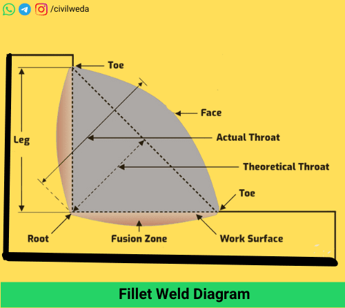
In steel construction, many joints have to be made where two members meet at an angle. A fillet weld is the most commonly used for connecting the members. It is simply a deposit of weld metal that fills the corner formed between the two members, as shown in the above figure.
When you look at its cross-section, it appears roughly triangular in shape. Fillet welds are generally used in T-joints, lap joints, and corner joints. Depending on the requirement of the joint and the way the weld metal cools, the exposed face of the weld may look concave, convex, or almost flat.
Codes such as IS 800:2007 specify the size and quality requirements for fillet welds, because the strength of the connection depends on various factors like leg length and the effective throat thickness of the weld size of weld etc.
Types of Fillet Weld
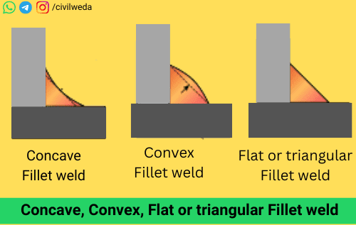
These welds can appear in different shapes. The shape of the weld depends on how the molten weld metal is placed and how it cools after solidification. In construction and structural work, three main forms of fillet welds are commonly used, i.e. concave, convex, and flat fillet welds. All three have the same basic purpose of joining two members, but their shape influences the strength and behaviour of the welded connection. The figure shows the three basic shapes of a fillet weld – concave, convex, and flat.
Concave Fillet Weld
A concave fillet weld has its exposed face curved inward. This shape often develops when the weld materials are deposited in several layers and the final passes contract as they cool. The inward curve slightly reduces the throat thickness, which means that the weld’s static load-carrying strength is somewhat lower than that of a convex weld.
However, the smooth concave-shaped fillet weld reduces stress concentration at the weld toe, which is an advantage when the joint is subjected to repeated or cyclic loads, bridge girders, crane structures, and other components that face vibration.
Convex Fillet Weld
Convex weld has an exposed face that bulges outward side. It is generally formed when more weld metal is deposited in the joint.
The extra weld metal increases the throat thickness, giving the weld a higher capacity to resist static or steady loads. As the weld metal cools, it contracts slightly and produces mild compressive stress on the outer face, which can help in resisting surface cracks. Convex welds, as shown in the figure, are often selected for heavily loaded joints in columns, trusses, and stiffeners of plate girders. Convex Weld is important where higher static strength is required.
Flat Fillet Weld
Flat weld has an exposed face that lies almost level with the adjoining surfaces, so it looks like a triangular shape as shown in the above figure. It is commonly produced under controlled shop welding conditions or with automated welding processes. A flat weld provides a balanced performance between concave and convex shapes. Flat Weld is often used in machine-welded joints where uniform appearance and consistent strength are required.
Notes Points:
- The shape of the weld affects its throat thickness and load-carrying capacity of joints.
- In general, concave welds perform better under cyclic or fatigue loading, while convex welds are more suitable for static, heavy loads.
General Specifications of Fillet Weld
As per IS 800:2007 (You can download the IS 800:2007 from the official site of BIS), the strength and performance of the weld depend on a few important terms, such as the size of the weld, leg length, maximum and minimum limits, effective throat thickness, effective length, effective area, and overlap length. A detailed explanation is given below:
Size of Fillet Weld
The size of a weld is specified by its leg length. In simple terms, the size represents the minimum dimension needed to give the joint adequate strength. In simple words, we can say that the weld size ensures that the joint can safely transfer the required loads.
Leg Length
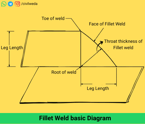
The leg length is measured from the point where the two members meet (root) to the outer edge of the weld (toe). In most cases, it is visualised as the side of the largest right-angled triangle that can be inscribed inside the weld cross-section. This is shown in the figure.
For joints made between members of unequal thickness, the leg length is generally based on the thickness of the thinner member. In practical work, this dimension is critical because it directly affects the effective throat thickness and the strength of the weld.
For example, in a right-angle joint, the leg length is the distance from the root of the weld to the toe of the weld, as shown in the figure.
Maximum Size of Fillet Weld
The maximum size of a weld is limited to prevent overheating and to ensure proper fusion of the joint. As per IS 80:2007, the maximum size of the weld is taken as the thickness of the thinner member minus 1.5 mm. When welding is done at a rounded edge or toe of a rolled section, the maximum size should not exceed 75% of the thickness of the section at the toe. It helps to avoid excessive heat build-up and distortion of the connected members.
Minimum Size of Fillet Weld
A fillet weld also needs to have a certain minimum size to ensure proper fusion with the base metal. If the weld size is too small, the heat generated during welding may not be sufficient to penetrate and bond with the thicker member. So, as per the IS 80:2007, the minimum size of a fillet weld is related to the thickness of the thicker member, not the thinner member being joined, and should never be less than 3 mm.
The detailed values of the minimum weld size as per the IS 800-2007 are given in the table below.
| Thickness of Thicker Member (mm) | Minimum Size of Fillet Weld (mm) |
|---|---|
| Up to 10 | 3 |
| 10 – 20 | 5 |
| 20 – 32 | 6 |
| 32 – 50 | 8 – 10 (depending on first run) |
Effective Throat Thickness
The effective throat thickness is the shortest distance from the root of the weld to the face of the weld, measured across the theoretical throat of the triangular cross-section. Effective throat thickness is the most important dimension for calculating the load-carrying capacity of a fillet weld.
As per IS 800:2007, the effective throat thickness:
- Should not be less than 3 mm
- Should generally not exceed 0.7 × t, where t is the thickness of the thinner plate
- May be taken as 1.0 × t in certain special cases
Mathematically, effective throat thickness is given by, - Effective Throat Thickness =K×S
Where: - S = Size of the fillet weld (leg length)
- K = Constant which depends on the angle between the fusion surfaces (as given in the table below)
| Angle between fusion faces (in degrees) | value of K |
|---|---|
| 60 – 90 | 0.70 |
| 91 – 100 | 0.65 |
| 101 – 106 | 0.60 |
| 107 – 113 | 0.55 |
| 114 – 120 | 0.50 |
Effective Length of Fillet Weld
The effective length is the actual length of the weld that contributes to the strength of the joint. It is defined as the total length of the weld minus twice the weld size (2S). In practice, the effective length should not be less than four times the size of the weld. End returns are often provided to reduce stress concentration, and their length is usually taken as twice the weld size.
Mathematically Effective Length of Weld is given by
- lₑff = L – 2S
where, - lₑff = Effective Length of Weld
- S = Size of weld
Effective Area of Fillet Weld
The effective area of a weld is obtained by multiplying the effective length by the effective throat thickness. The effective area of a weld is the area that actually resists the applied loads in the joint. The effective area of the weld is used in design calculations to check whether the weld is strong enough to carry the loads safely.
Mathematically effective area of the weld is given by,
- Aₑff = lₑff ×tₜ
Where, - Aₑff = Effective area of the weld
- lₑff = Effective length of the fillet weld
- tₜ = Effective throat thickness of the weld
Overlap Length
When two steel members are joined by welding in a lap joint, they must overlap by a certain minimum distance. As per IS 800:2007, the overlap should not be less than four times the thickness of the thinner member or 4 mm, whichever is greater. Adequate overlap length ensures that the joint transfers the load efficiently without local bending at the edges.
Note Points
- The above specifications ensure that the welded joint is strong, safe, and durable.
- Designers and site engineers must always follow the guidelines of IS 800:2007 and other relevant standards while deciding on weld size, leg length, and throat thickness etc, as mentioned above specification.
- Proper adherence to these parameters helps prevent failures and ensures the long-term performance of the steel structure.
Applications of Fillet Weld in Civil Engineering
Fillet welds are the most commonly used type of weld in steel structure design. Their simple shape and ease of application make them suitable for a wide range of structural connections. The reliability of a welded joint depends on selecting the right type and size of weld for each situation. Some of the major applications of this weld in civil engineering are described below.
Structural Steel Frames
These welds are widely used to join the members of structural steel frames. They provide strong connections between beams, columns, and stiffeners without the need for complex edge preparation. In many cases, site welders use fillet welds for assembling prefabricated steel components during erection.
Bridges and Trusses
In steel bridges and truss structures, various members are required to connect with gusset plates, angle sections, and stiffeners. Fillet welds are preferred in such cases because they can be applied at right-angle joints. It distributes stresses smoothly and saves time during the welding of the member.
Industrial Sheds and Warehouses
The construction of industrial sheds, warehouses, and workshops often involves connecting steel plates and sections. So, here fillet welds are particularly suitable for these joints since they provide adequate strength and can be executed efficiently on site.
Tanks, Silos, and Storage Structures
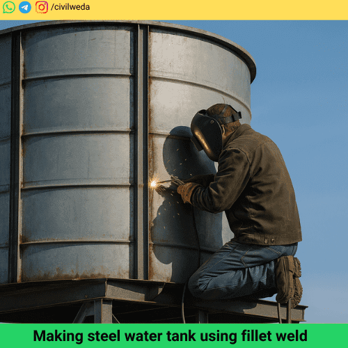
In cylindrical (water) tanks, silos, and hoppers, fillet welds are frequently used to connect vertical stiffeners, ring beams, and sheet plates. Adequate strength of welds helps in achieving leak-proof joints and ensures uniform load transfer. A typical image of the making of a steel water tank is shown in the figure.
Learn more about Waterproofing with Bitumen to protect such structures.
Shipbuilding and Heavy Equipment
Beyond buildings, water tanks, silo, workshops and bridges, fillet welds are also widely applied in the making of shipbuilding, cranes, material handling equipment, and rail wagons. Their ability to join thick and thin members at various angles makes them a versatile choice in these industries as well.
Advantages and Limitations of Fillet Weld
Fillet welds are among the most preferred welding methods in steel construction because they are simple to apply and versatile in use. However, like every technique, they have both strengths and certain limitations that engineers must keep in mind during design and construction. Here we discuss advantages and Limitations (disadvantages) of this Weld, so let’s get started-
Advantages of Fillet Weld
- Simple Preparation
These welds do not require the edges of plates or sections to be bevelled. This reduces the time and cost of preparing joints as compared to butt welds. - Ease of Application
They can be applied easily in various joint configurations, such as T-joints, lap joints, and corner joints, even at construction sites. - Economical for Field Work
Because of their simple geometry and relatively quick execution, welds save both labour time and fabrication cost. - Effective for Thin to Medium Sections
Fillet welds work efficiently for plates and sections of moderate thickness, which are common in bridges, trusses, and industrial buildings. - Good Stress Distribution in Properly Designed Joints
When correctly proportioned and applied, fillet welds distribute stresses smoothly along the length of the joint, reducing stress concentration.
Limitations of Fillet Weld
- Lower Penetration than Butt Welds
Since the fusion occurs only at the surfaces in contact, fillet welds do not achieve the deep penetration of a properly compared to a butt weld. - Sensitive to Quality of Execution
Poor workmanship, such as incomplete fusion or uneven weld size, can significantly reduce the strength of the joint. - Prone to Fatigue Cracks under Cyclic Loading
If not designed with adequate throat thickness or if the weld face is too convex, stress concentrations may lead to fatigue cracking in vibrating or cyclically loaded members. - Limited Suitability for Very Thick Sections
For heavy plates and large structural members, fillet welds alone may not provide the required strength, and combined or full-penetration butt welds may be necessary. - Inspection Can Be More Difficult
Detecting internal defects in fillet welds can be harder compared to butt welds, as the weld metal is deposited in the corner of the joint.
Read our other Articles
Bulking of sand
Seasoning of timber
Geopolymer concrete
Effective span
Pile foundation
Conclusion
You now know why a certain size is chosen, why some joints need a convex face, and why… If you look at most steel structures around us, from simple sheds to long-span bridges, fillet welds are everywhere. They are popular because they are quick to apply and usually strong enough for the job.
The real key to a good weld is not just its size on paper but how well it is made in the field. Details such as leg length, throat thickness, size of weld, and proper overlap etc., are very important. That’s why engineers refer to standards specifications like IS 800: 2007 is used and check every critical joint during construction. For anyone learning steel design or working on site, understanding these basic points is important. It helps ensure inspection cannot be skipped.
When the design is sound and the workmanship is careful, these welds remain one of the simplest and most reliable ways to connect steel members together whether it’s a truss in a factory roof or a girder in a bridge.
FAQs on Fillet weld
1. What is a fillet weld?
This type of weld is used to join two metal surfaces at approximately right angles to each other. It is commonly triangular in cross-section and widely used in structural steel connections.
2. What is the effective throat thickness of the weld?
The effective throat thickness is the shortest distance from the root of the weld to the face of the weld. It is considered the minimum strength parameter of the weld.
3. What is the maximum size of a fillet weld?
According to IS 800:2007, the maximum size should not exceed the thickness of the thinner member at the joint. The maximum size of a fillet weld depends on the thickness of the member being joined.
4. What is the minimum size of a fillet weld?
The minimum size of the weld ensures proper heat dissipation and joint strength. For example, for a plate of 10 mm thickness, the minimum size is 3 mm as per Indian standards.
5. What are the common types of fillet weld?
The three main types of fillet welds are: Concave, Convex, Flat fillet weld.
Thank You for Reading! 🙏
We hope this article helped you clearly understand the Fillet weld in civil engineering. If you found this complete article useful, please share it with your friends and university students. For more informative posts on civil engineering topics, stay connected with Civil Weda. 🚀